The smaller question and the larger one
Between 1900 and 2000, the tolerance a workshop could reliably hold on a machined part fell by something like three orders of magnitude — the difference between a dimension good to a few thousandths of an inch and one good to a few millionths. The conventional explanation reaches for the machine tool: better lathes, better grinding wheels, numerically controlled slides. That answers the smaller question. A machine cannot hold a tolerance nobody can verify it is holding, and at every stage the binding constraint was metrology — the instruments and standards used to measure a difference — with machining following once the measurement existed to certify it. The same decades that gave engineering shops their screw-cutting lathes and interchangeable parts also produced a quieter lineage: the wrung gauge block, the mechanical comparator, and the redefinition of the metre itself — three answers to one question, how small a difference can reliably be seen.
A block that becomes its own standard
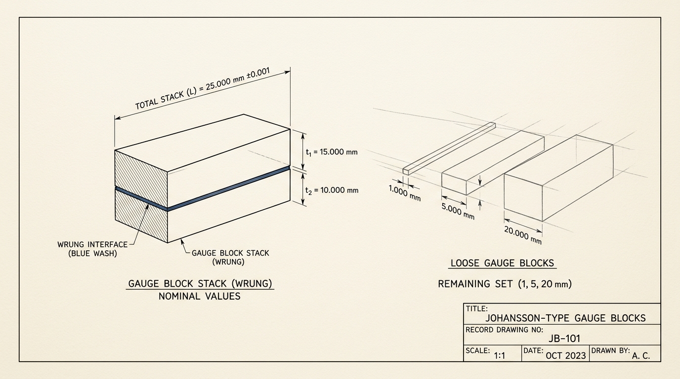
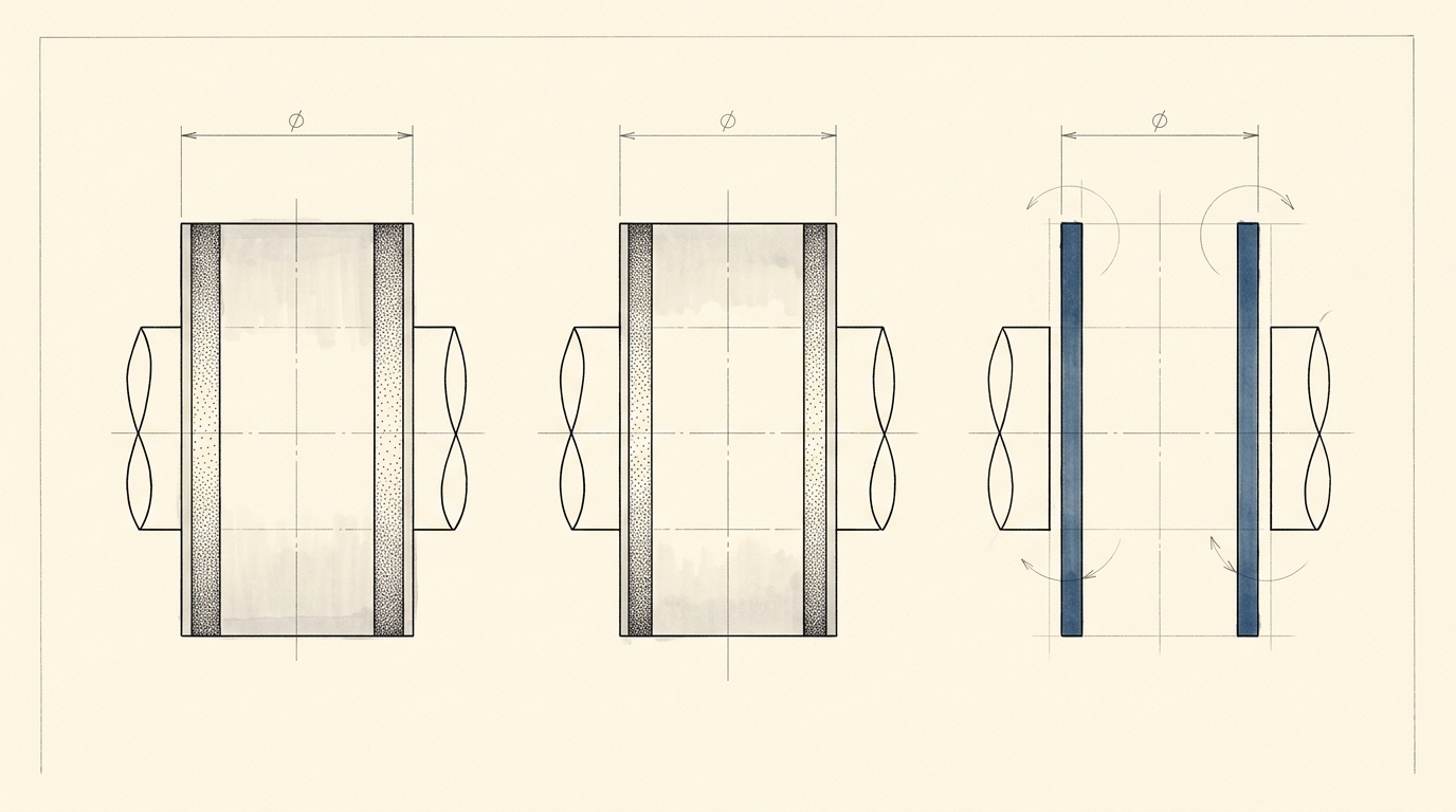
The pivotal device is almost absurdly simple. In 1896 the Swedish rifle-factory inspector Carl Edvard Johansson proposed that a small set of steel blocks, ground flat and parallel to a controlled tolerance, could be combined by arithmetic into any working length a shop needed — four blocks sized 1, 2, 4 and 8 millimetres, wrung together in combination, span every millimetre size from 1 to 15 [1]. What made the idea work was a phenomenon Johansson had not set out to invent. Two gauging faces lapped flat enough and pressed together with a trace of oil do not merely touch; they wring, adhering with a force out of proportion to the light contact, so the stack behaves, for measurement purposes, as one piece of steel. The wringing film itself is only around 25 nanometres thick — small enough, at the tolerances of the day, that block lengths could simply be added with no correction for the interface [1].
Wringing is the whole mechanism by which a length standard becomes transferable. A master artefact, however precisely made, is useless to a distant workshop unless copies can be manufactured and checked to the same standard, and gauge blocks solved that by letting any shop build its own reference from a purchased set, then keep it honest by comparison back to a calibrated master [2]. Within two decades the US National Bureau of Standards was manufacturing an American equivalent, and gauge blocks had become wartime strategic goods [2].
Reading a difference, not a length
Gauge blocks alone measure nothing; they are compared against. The instrument performing the comparison is a mechanical comparator, and its logic is the second idea this history turns on: precision comes from comparing an unknown against a known standard, not from reading an absolute position off a scale. A bench comparator carries a spring-loaded measuring stylus bearing on the block under test, its small displacement converted by a transducer coil into a signal displayed, after amplification, on a dial graduated in length units [1]. Zeroed against a reference block, then substituted with the test block, the dial reads only the difference between the two — the comparator’s own geometry, however imperfectly known, applies equally to both readings and cancels.
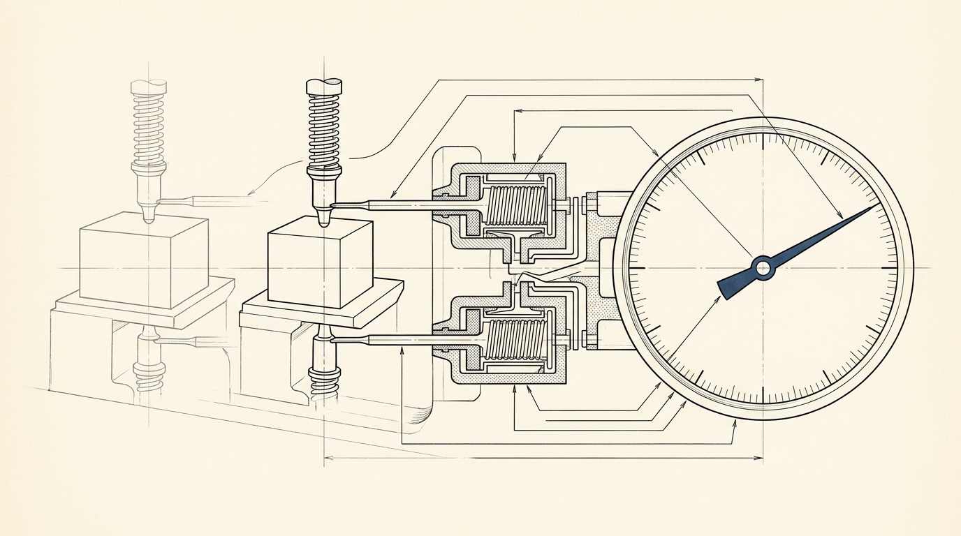
This is why comparators track the progression of masters rather than running ahead of it: a comparator is only as good as the reference it is zeroed against. NIST’s bench comparators still use this design, refined mainly in transducer accuracy and contact-force control, both correctable to a few nanometres once characterised [1].
The metre stopped being a piece of metal
The comparator solves local transfer, one shop’s blocks against another’s; it does nothing for the deeper question of what anchors the master itself. For a century after 1889 the answer was a physical bar: the 1st General Conference on Weights and Measures sanctioned a specific length of platinum-iridium alloy as the metre [5], an artefact standard in the fullest sense. Its length was whatever it was, and the resolution establishing it stated no independent measurement uncertainty at all, because nothing outside the bar existed to check it against except copies made from it — a standard that could be trusted but not improved.
| Definition of the metre | Adopted | Physical basis | Supported uncertainty |
|---|---|---|---|
| International Prototype Metre | 1889, 1st CGPM | a bar of 90% platinum, 10% iridium, two scribed lines | not independently stated — the bar was its own reference |
| Krypton-86 wavelength | 1960, 11th CGPM | 1,650,763.73 vacuum wavelengths of the 2p10–5d5 transition | plus or minus 4 x 10⁻⁹ relative, in the best realisations [8] |
| Speed of light | 1983, 17th CGPM | c = 299,792,458 m/s exactly; length is now a derived unit | exact by definition; best laboratory realisation about 2.5 x 10⁻¹¹ relative [3] |
In 1960 the 11th CGPM broke the dependence on a single object, redefining the metre as a stated number of wavelengths of light from a krypton-86 discharge lamp — reproducible anywhere a suitable lamp and interferometer exist, with no journey to a vault required [5]. The 1983 redefinition went further still, fixing the speed of light at exactly 299,792,458 metres per second and making the metre a derived unit of time [6]. Neither change altered the metre’s length by any amount a shop would notice; each changed only how independently that length could be reproduced.
Counting wavelengths
Turning a wavelength into a usable industrial standard required an instrument, and the workhorse is the interferometer — for gauge blocks, the Kösters-type design still used at national laboratories today [1]. A wrung gauge block sits on a flat steel platen; light from a stabilised source splits, one beam reflecting from the platen and the block’s top surface, the other from a fixed reference path, recombining to form fringes. Because the block stands proud of the platen by its own length, the block’s fringes are offset from the platen’s by a fraction that, once the whole number of intervening wavelengths is known, fixes the block’s length to a small fraction of one wavelength [1].
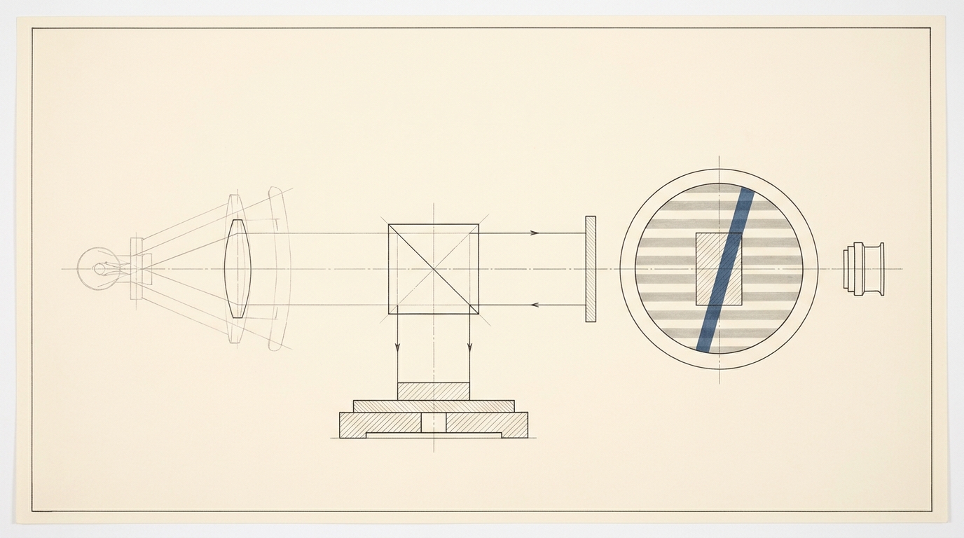
This is the same comparator logic, one level down: the interferometer measures the block against the wavelength of light, which after 1960 was itself the legal definition of length. An iodine-stabilised helium-neon laser, the recommended radiation for realising the metre today, is known to a relative uncertainty of about 2.5 x 10⁻¹¹ [3], accurate enough that the expanded uncertainty on a calibrated short gauge block at NIST had fallen by 2001 to 0.008 micrometres — an improvement its own metrologists describe as two orders of magnitude over the institution’s working lifetime [3].
The error budget
Below a few micrometres a different problem dominates, one no single better instrument solves: steel expands. A gauge block’s own length depends on its temperature, and the coefficient is not small — gauge-block steel grows by about 11.5 parts per million for every degree Celsius, so a 100-millimetre block lengthens by 1.15 micrometres for a single degree of warming [1].
That is why dimensional metrology fixed 20°C as the reference temperature for every length standard, and why NIST’s gauge-block laboratories hold the room within a tenth of a degree of it, wrap long blocks in reflective film to equalise radiant heating, and require hours of thermal soaking before a comparison is trusted [1]. Past this point the workpiece, the comparator and the room itself are all moving on the scale that matters, and the discipline changes character: no longer a search for one dominant error to eliminate, but the management of a budget of small, simultaneous errors — thermal, elastic, vibrational — each characterised and corrected for, or held below the level that matters. Even a 500-millimetre block held within a tenth of a degree of 20°C still carries a thermal uncertainty of several tenths of a micrometre once the expansion coefficient’s own uncertainty is included [1] — a well-controlled room shrinks the budget; it never eliminates it.
A thousandfold in a century
Put the pieces together and the shape of the century appears in numbers assembled for an industrial workshop report, not a retrospective history. In 1992 NIST convened manufacturers to compare the tolerances industry was designing to against the calibration accuracy the laboratory could supply, and the trend was blunt: precision-manufacturing tolerances were tightening by roughly a factor of three every ten years, from a design tolerance of about 20 micrometres in the 1970s toward a projected 1 micrometre by 2000, with the required calibration accuracy falling in step, from 1.25 micrometres to 0.05 micrometres over the same interval [4].
| Era | Representative achievable tolerance | Enabling measurement instrument |
|---|---|---|
| c. 1850, ordinary workshop practice | order of 1.6 mm (1/16 in) | eye and rule; no calibrated comparator existed |
| c. 1900–1920, interchangeable-parts manufacture | order of a few micrometres, held via wrung stacks | Johansson combination gauge blocks wrung to a reference |
| 1970s, precision-tolerance manufacturing | 20 µm design tolerance; 1.25 µm required calibration accuracy | mechanical comparators against interferometrically calibrated masters |
| 2000, same benchmark (industry projection) | 1 µm design tolerance; 0.05 µm required calibration accuracy | CMMs referenced to laser-interferometer masters |
| 2001, NIST primary length standards | 0.008 µm expanded uncertainty, short gauge blocks | laser (iodine-stabilised He-Ne) gauge-block interferometry |
- Design tolerance
- Required calibration accuracy
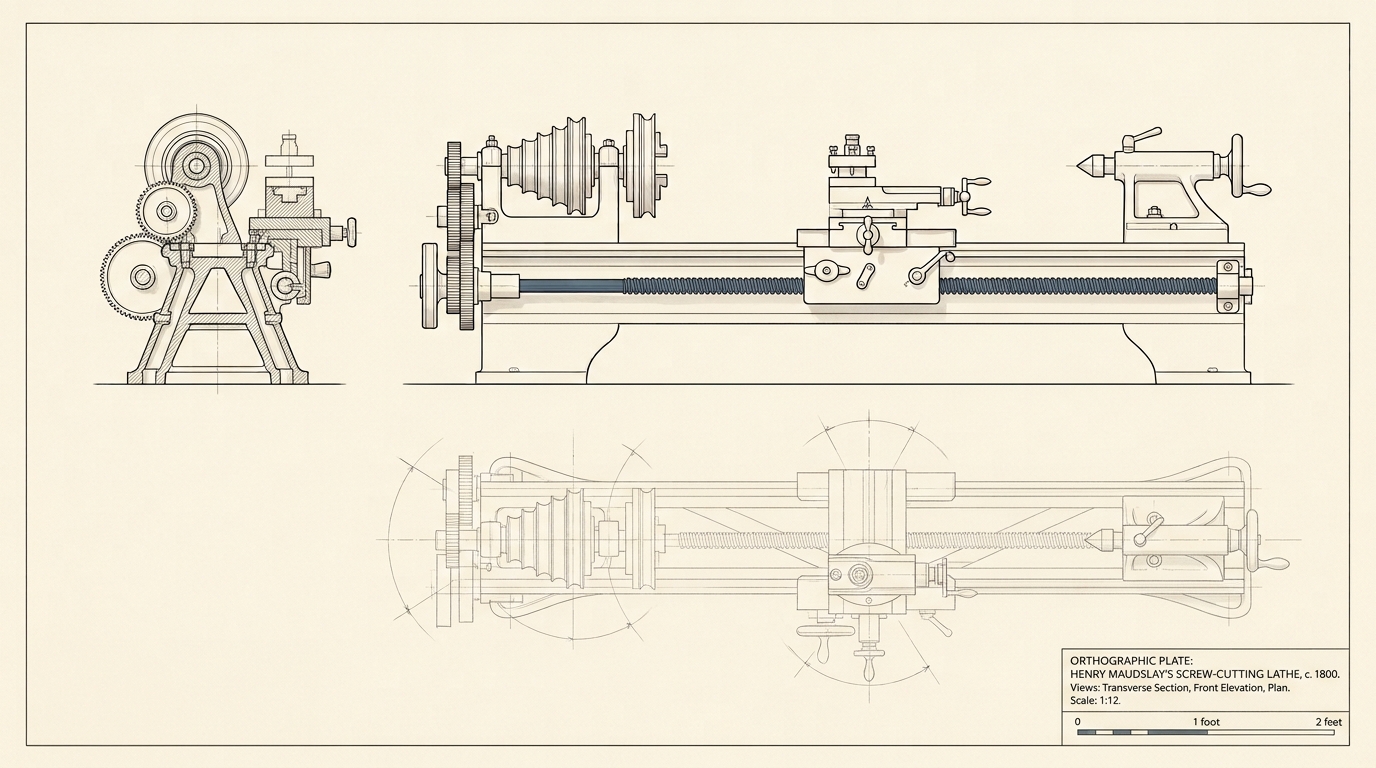
The earliest row is deliberately an order-of-magnitude figure, not a measured one: before Joseph Whitworth’s true planes and end-measuring machine of the 1840s, a sixteenth of an inch (about 1.6 mm) was reckoned ordinary workshop accuracy, and Whitworth’s instrument reportedly registered the expansion of an iron bar caused by the touch of a finger [9] — a measuring machine, distinct from the screw-cutting lathes that made interchangeable machining possible in the same workshops. A separate, peer-reviewed account of machining accuracy itself, charted by Taniguchi in 1983, shows ordinary, precision and ultra-precision machining each declining on its own roughly parallel curve, normal shop tolerances crossing into the sub-micrometre range only as the century closed [7]. Machining did tighten — but at every point, the tolerance claimed was one somebody could certify.
That is the argument in its narrowest form. A workshop cannot hold a tolerance it cannot verify; it can only claim one. What fell across the century, by something close to three orders of magnitude on the industrial side and considerably more at the reference laboratories, was not the smallest cut a tool could make but the smallest difference an instrument could certify as real — first between two wrung blocks, then a stylus and a dial, then two paths of light.
What actually moved
None of this claims machining stood still while measurement did the work; the two advanced together. But the sequence of firsts runs consistently one way: wringing before wrung blocks could be trusted, the comparator before its readings could be certified, the krypton line and then the laser wavelength before either could be cut to. Measurement set the ceiling, and manufacturing, decade by decade, climbed up to meet it.