What a bench, not a hall, actually verifies
An earlier piece in this series toured the equipment: spine switches with their port cages part-populated, transceivers going in and out under bale latches, drive caddies and busway feeding rows of accelerator pods. That piece asked how a model gets split across a fabric and what each way of splitting it costs in traffic. This one asks a narrower and more literal question: when a training job issues an all-reduce, what actually happens to one byte between the instant it leaves one accelerator’s memory and the instant it lands, correctly, in another’s?
The honest answer is not a diagram of arrows between boxes. It is a stack of specific mechanisms, each solving a specific physical or logistical problem, each verified on a bench with a probe or a bit-error-rate tester before it is trusted in a live fabric: a queue-pair state machine that lets a network adapter act on a remote memory address without asking the remote processor’s permission; an encapsulation trick that lets an InfiniBand-style transport ride ordinary Ethernet; a flow-control mechanism that manufactures losslessness on a medium that does not have it natively; a family of congestion signals tuned to stop a queue from filling before that flow control ever has to act; a switch datapath that can perform part of a reduction while a packet is still in flight; and, underneath everything, a laser or a copper pair encoding bits at a rate that a receiver can actually decode. This article follows that stack from the accelerator’s memory outward to the fiber, staying at the level of mechanism rather than topology.
Two protocols share a room, not a wire
The fastest links in a modern accelerator pod are not, strictly speaking, a network in the sense a systems engineer means by the word. NVIDIA states that its sixth-generation NVLink delivers 3,600 GB/s of bidirectional bandwidth per GPU and that an NVLink Switch domain can aggregate 260 TB/s across 72 GPUs “fully connected” in “a non-blocking compute fabric” supporting “full all-to-all communication” [12]. Those are vendor figures for peak link capability, not measured application throughput, and should be read as such. What matters for this article is not the number but the kind of thing being described: NVLink is closer to a memory bus that happens to span multiple packages than to a network in the sense Ethernet or InfiniBand are networks. A load or store issued by one GPU’s memory controller against a remote address inside the NVLink domain is satisfied, in effect, the way a local memory access is — no packet header is being interpreted and routed hop by hop by software running anywhere.
Step outside that domain and the model changes completely. A scale-out fabric — Ethernet or InfiniBand carrying RDMA between nodes — is message-passing: an explicit unit of data, framed with headers that name a destination and a connection, handed to a switch that makes an independent forwarding decision for that unit, with no shared address space assumed anywhere along the path. The rest of this article is almost entirely about that second kind of fabric, because it is where nearly all of the interesting, under-explained mechanism lives: how a message-passing network can be made to behave, for the purposes of a collective operation, almost as if it were an extension of GPU memory.
What “bypassing the CPU” actually means
“RDMA bypasses the CPU” is the single most repeated claim about this whole stack, and it is usually left unexplained. The mechanism is specific enough to state plainly.
An RDMA-capable NIC exposes a queue pair to software: a send queue and a receive queue, each a ring of descriptors the NIC’s own hardware walks independently once told to start. To issue an operation, software (or, in practice, a collective communication library acting on its behalf) writes a descriptor into that ring describing a local buffer and, for a one-sided operation, a remote virtual address that the destination has previously registered and authorized for remote access. It then writes to a small memory-mapped register on the NIC — conventionally called ringing the doorbell — which tells the NIC’s hardware that a new descriptor is ready. From that point, the NIC’s own transport engine owns the operation: it performs the local DMA to fetch or place the data, frames the network packets, tracks sequence numbers and retransmission, and reports completion. No system call and no host-side interrupt is required per packet.
The part that actually deserves the word “bypass” is what happens at the far end of a one-sided operation. Anuj Kalia, describing the RDMA research this section draws on, put it plainly: “clients send RDMA read/write requests to a remote server. The server’s RDMA NIC performs local Direct Memory Access (DMA) read/write operations in response to client requests, and sends a reply” [1]. For an RDMA WRITE or READ, the remote NIC satisfies the request out of its own hardware memory-translation state — it does not schedule the remote CPU, wake a thread, or run any software on that side at all. That is a genuine architectural difference from a two-sided SEND/RECV pair, where the receiving side must have already posted a matching receive descriptor that its own software consumes; two-sided operations still avoid a kernel crossing on a well-tuned path, but they are not silent to the remote side the way a one-sided WRITE is.
For an accelerator, one more piece has to be true for any of this to matter: the buffer named in that descriptor has to be able to live in the accelerator’s own memory rather than in host RAM, or every collective operation would still pay a staging copy through the CPU on both ends. NVIDIA’s GPUDirect RDMA documentation describes exactly this extension: “a direct path for data exchange between the GPU and a third-party peer device using standard features of PCI Express,” where the two devices “must share the same upstream PCI Express root complex” and the NIC issues reads and writes to the GPU’s PCIe BAR address “in the same way that they are issued to system memory” [9]. In practice that means the NIC’s DMA engine addresses a window into the GPU’s own high-bandwidth memory directly, and a collective library can post a WRITE whose source or destination is literally inside GPU memory with no host-memory staging copy at all — the mechanism above and this one are what “GPU-to-GPU across the network” actually means in hardware terms, not just in a diagram.
Borrowing InfiniBand’s transport, and paying for it in pause frames
Native InfiniBand solves the loss problem at the link layer, structurally, before any of the above comes into play. Its link-layer flow control is credit-based: a sender tracks how many receive buffers the far end of a link has advertised as free, on a given virtual lane, and will not transmit onto that lane until credit is available — a mechanism documented for the IEEE 802.1 working group specifically because Ethernet has no native equivalent [15]. The result is a fabric that is lossless by construction rather than by policy: a packet is never dropped for lack of buffer space, because the sender was never permitted to send it without buffer space already reserved.
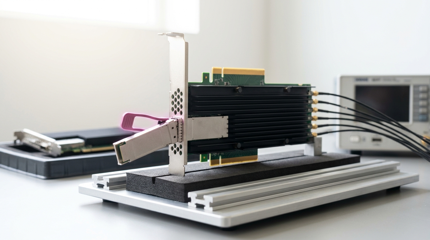
Ethernet was not built this way, and RDMA over Converged Ethernet exists precisely to carry InfiniBand’s transport semantics — queue pairs, packet sequence numbers, the reliability guarantees applications depend on — over a switching fabric that was not designed with any of that in mind. RoCEv2 does this by encapsulation rather than by redesigning Ethernet: NVIDIA’s own RoCEv2 documentation describes routable RoCE packets as carrying “an IP header which allows traversal of IP L3 Routers and a UDP header that serves as a stateless encapsulation layer for the RDMA Transport Protocol Packets over IP” [4], a design the InfiniBand Trade Association introduced specifically to let RoCE fabrics extend “beyond a single Layer 2 subnet by supporting routing across Layer 3 networks” [3]. Strip the headers off a RoCEv2 frame and what remains is unmistakably InfiniBand: the same base transport header, the same queue-pair addressing, the same integrity check, now sitting inside an ordinary UDP datagram that any commodity Ethernet switch can forward without knowing anything about RDMA at all.
But encapsulating the transport does not manufacture the underlying losslessness that transport was designed to assume. Ethernet has to be given that property separately, and the mechanism for doing so is Priority Flow Control, standardized as IEEE 802.1Qbb: a per-priority variant of the ordinary Ethernet PAUSE frame that lets a receiver “eliminate frame loss due to congestion” on one traffic class without halting the others sharing the same physical link [7]. A switch facing a filling egress queue for the RDMA priority class sends a PAUSE specifically for that class upstream; the sender for that class stops, other classes keep moving, and no packet is dropped. It is a real guarantee, bought at a real cost: because PFC pauses an entire priority class on an entire link rather than a single flow, one congested destination can back up traffic behind unrelated flows sharing its class and its upstream link — head-of-line blocking that the researchers who built DCQCN cite explicitly as a reason PFC alone “can lead to poor application performance due to problems like head-of-line blocking and unfairness” [2]. Everything in the next section exists to keep that blunt, per-hop mechanism from being the thing actually managing everyday traffic.
Marking before dropping: the congestion control stack
Priority Flow Control is a backstop, not a scheduler. If every large flow relied on it to regulate itself, throughput would collapse into the pause-and-release rhythm of a mechanism built to prevent loss, not to allocate bandwidth fairly or efficiently. The layer that has to act earlier and more precisely is congestion control, and on a modern RDMA fabric it is built out of three mechanisms stacked on top of each other.
The foundation is Explicit Congestion Notification, standardized in RFC 3168: instead of a router signaling congestion only by dropping a packet, it may instead set a Congestion Experienced codepoint in the packet’s header and forward it anyway, letting the receiver echo that mark back to the sender as a request to slow down “instead of exclusively relying on packet drops” [13]. That single idea — mark, don’t drop, and let the endpoint react — is the building block everything above it reuses.
Data Center TCP refined the marking policy for the latencies and buffer sizes actually found inside a datacenter. Its authors describe DCTCP as a scheme that “leverages Explicit Congestion Notification (ECN) in the network to provide multi-bit feedback to the end hosts” rather than the single congestion bit ordinary TCP effectively gets from a drop [14]. The practical mechanism is a threshold rule applied at each switch queue: writing
so the sender receives, over many packets, a running estimate of what fraction of its recent traffic found the queue already over threshold — a proportional read on the severity of congestion rather than a single bit saying only that congestion happened somewhere.
DCQCN carries that same ECN-based idea onto RoCEv2 specifically, as a rate-based algorithm rather than TCP’s window-based one, tuned for a fabric where PFC already exists underneath it as the mechanism of last resort. Its authors describe it as “an end-to-end congestion control mechanism” whose parameters — including switch buffer marking thresholds — were tuned “using a fluid model,” evaluated on “a 3-tier Clos network testbed” and, as of their report, “implemented in Mellanox NICs, and being deployed in Microsoft’s datacenters” [2]. The point of the whole arrangement is to get senders to back off from ECN marks quickly enough, and far enough upstream of a full queue, that PFC’s blunt per-priority PAUSE rarely has to be the thing actually doing the work — it stays available as insurance rather than becoming the fabric’s everyday rate limiter.
The newest layer in this stack changes the assumption that a flow uses one path at all. The Ultra Ethernet Consortium’s Specification 1.0, released 11 June 2025, defines a stack spanning “applications, transport protocols, congestion control, direct memory access, Ethernet link and PHY technologies, and network security,” including what the consortium describes as “modern RDMA for Ethernet and IP” aimed at scaling to “millions of endpoints” [10]. The transport paper behind it, from Hoefler and co-authors, describes Ultra Ethernet Transport as spreading a single transfer’s packets across multiple available paths rather than pinning it to one, combining that multipathing with ECN-based marking, packet trimming under severe congestion, and receiver-driven credit that lets the destination regulate how much is in flight toward it, with loss handled by selective retransmission of only the missing packets rather than the whole window. Reordering that results from using several paths at once is handled at the receiver rather than avoided by construction. Whether deployed silicon delivers that design at the claimed scale is a separate question from what the specification describes; at present this is a specification and an accompanying architecture paper, not yet a track record.
How a collective operation actually crosses the fabric
Take the canonical case: a ring all-reduce across
What is genuinely new at the fabric level is the option to have some of the arithmetic happen inside the network rather than only at the endpoints. NVIDIA’s SHARP technology works by “offloading collective operations from CPUs and GPUs to the network,” building an aggregation tree across the switches on the path so that data volume is reduced “as aggregation nodes are reached,” with a third generation supporting “multiple aggregation trees… over the same topology” for concurrent jobs sharing one fabric [5]. The academic version of the same idea, SwitchML, implements it on programmable switch hardware: “a communication primitive that uses a programmable switch dataplane to execute a key step of the training process,” aggregating model updates from multiple workers inside the switch itself, which its authors report speeding up training by up to 5.5x on the specific benchmark models they tested — a result specific to their setup, not a universal multiplier [6].
The mechanism underneath both is the same: a switch’s data-plane ALU holds a small per-flow accumulator, sums each child’s partial contribution into it as packets from different sources arrive, and only forwards the running total upward once its inputs for that step have arrived — so the number of bytes crossing the link above that switch reflects one aggregated vector rather than one full copy per contributing child. The reduction arithmetic that would otherwise have to run on every participating GPU or CPU instead runs once, in the switch silicon the data was already passing through. That is a different claim from anything about which topology or algorithm to route a collective over; it is a claim about which piece of hardware performs the addition, and it is possible only because a collective’s structure — many partial sums converging on one result — happens to be exactly the shape a network device can compute on in flight.
The physical layer underneath every packet
Every packet described above eventually has to leave a chassis as an electrical or optical signal, over one of a small number of physical media, and the choice among them is dictated by physics that has nothing to do with any protocol discussed so far.
Modern high-rate Ethernet lanes use PAM4 modulation: instead of encoding one bit per symbol as ordinary NRZ signaling does, PAM4 uses four distinct voltage levels to encode two bits per symbol, so a lane’s bit rate runs at twice its baud (symbol) rate rather than matching it one for one. Writing
which is exactly the relationship documented for real 400G optics: a 26.5625 Gbaud lane carries 53.125 Gb/s in an eight-lane configuration, and a 53.125 Gbaud lane carries 106.25 Gb/s in a four-lane configuration [8]. That doubling is not free. Four voltage levels packed into the same signal swing compress the spacing between them, and the same documentation states that PAM4 “considerably reduces the signal-to-noise ratio” relative to NRZ — a roughly 10 dB penalty — which is exactly why a PAM4 transceiver requires a DSP performing equalization and clock recovery, paired with forward error correction, to be usable at all; the guide names RS(544,514) as the industry-standard code, correcting “up to 15 symbol errors within a single codeword” before a frame is considered lost [8]. The DSP inside a modern transceiver, in other words, is not an incidental feature. It is the component that makes the SNR penalty PAM4 imposes survivable at the rates these fabrics run at.
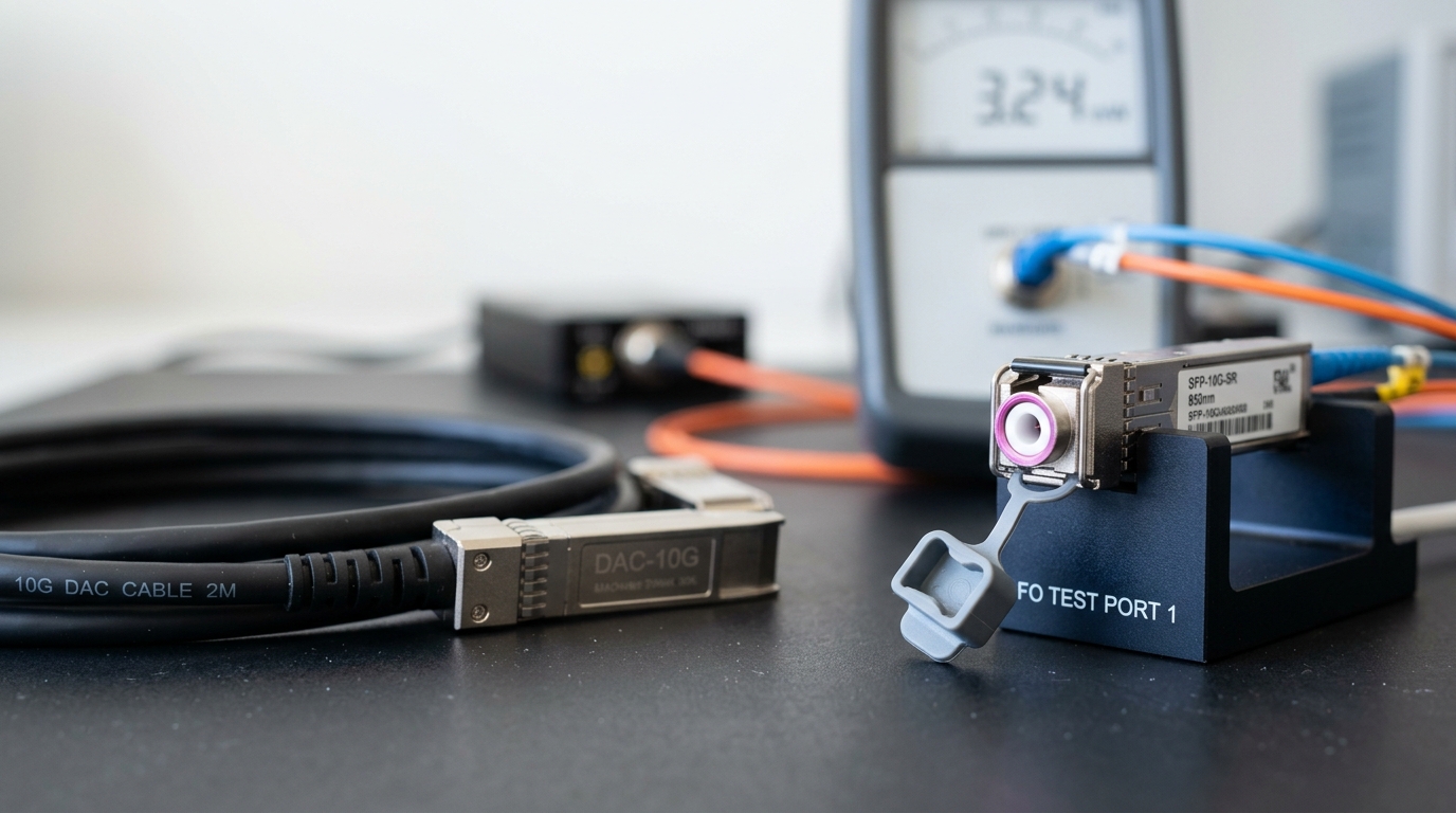
That physical layer also draws the line between the two kinds of interconnect discussed throughout this article. Passive DAC — direct-attach copper twinax — needs no laser and no DSP and draws well under a watt, but copper’s electrical attenuation rises steeply with frequency, so its usable reach collapses as lane rate climbs; at the highest current lane rates a passive copper link is workable only over a few meters, short enough for a rack-local hop and not much more. Active optical cables and pluggable transceivers convert to light at the connector, escaping copper’s attenuation curve entirely and reaching tens of meters to several kilometers depending on the fiber and optics used, at the cost of the power a laser and a DSP actually draw. That single physical fact — not any property of NVLink, InfiniBand, or Ethernet as protocols — is most of the reason a scale-up domain can stay electrical and copper-dense while anything that has to reach across a room or a hall is, almost by physical necessity, optical.
One write, start to finish
It is worth tracing a single hop of a ring all-reduce end to end, because every mechanism above is a piece of one continuous path and none of them is interesting in isolation. A collective library posts a work request naming a chunk of gradient sitting in one GPU’s HBM and a destination address in the next rank’s HBM, then rings the sending NIC’s doorbell. The NIC’s DMA engine reads that chunk directly out of GPU memory through the GPUDirect RDMA path — no host memory touched, no CPU scheduled. Its transport engine wraps the payload in a RoCEv2 packet, tagged with a queue-pair identifier and sequence number, encapsulated in the UDP/IP headers that let an ordinary switch forward it. A PAM4 SerDes drives that packet’s bits into an optical transceiver’s DSP, which frames them into four-level symbols, adds forward error correction, and puts them on fiber — or, for a short enough hop, straight down a DAC copper pair with no optics involved at all. Along the way, if the fabric supports it, a switch’s ALU may fold this packet’s contribution into a running sum before forwarding it, rather than passing a raw copy onward. ECN marks accumulate on the packet if a queue it crosses is building; DCQCN throttles the sender’s rate in response before Priority Flow Control ever needs to assert a pause. At the far end, the receiving NIC decodes the signal, checks the integrity field, matches the packet to its queue-pair state, and issues a DMA write straight into the destination GPU’s memory. A completion queue entry appears, and only at that point does the receiving GPU know the chunk is ready to be summed into the next step of the reduction. The CPU on either end touched none of it.
What would change this account
These are forecasts, kept separate from the sourced analysis above. Horizon: August 2030.
One. In-network reduction — the SHARP/SwitchML mechanism of folding partial sums into switch silicon rather than only at the endpoints — moves from an optimization available on specific fabrics to a default expectation on new large training clusters, as mixture-of-experts routing and larger world sizes make endpoint-side reduction arithmetic a bigger share of total cost. Observable indicator: whether newly announced large training fabrics disclose in-network aggregation as a standard feature rather than an optional add-on. Disconfirmed if large new deployments through the horizon continue to perform all reduction arithmetic at the endpoints with no in-network offload in general use.
Two. Multipath, receiver-driven transports in the Ultra Ethernet mold take meaningful share of new large RDMA fabrics from single-path, sender-throttled DCQCN-style deployments, because packet spraying removes the single-flow hot-link problem that motivated much of DCQCN’s design in the first place. Disconfirmed if DCQCN-on-RoCEv2 remains the majority mechanism on newly built large clusters through the horizon, with UET-class transports confined to pilots.
Three. PAM4 stops scaling at the highest lane rates without help, and either higher-order modulation (PAM6 or PAM8) or a shift toward linear or coherent optical designs inside the datacenter becomes necessary to keep raising per-lane rate without an unmanageable SNR penalty. Disconfirmed if PAM4 with conventional DSP and FEC remains the dominant scheme at the fastest lane rates deployed by the horizon with no adoption of higher-order or coherent techniques inside the datacenter.
Four. The boundary between scale-up and scale-out fabrics continues to be set primarily by copper’s attenuation curve rather than by any protocol choice, so scale-up domains grow mainly by fitting more accelerators inside a given electrical reach rather than by extending copper’s reach itself. Disconfirmed if a packaging or signaling advance lets copper links at current lane rates reach distances comparable to today’s optical links, erasing the physical reason for the scale-up/scale-out split.
None of these requires a discontinuity in the underlying physics or protocols. They follow directly from the mechanisms traced above: a reduction that can be performed once in the network instead of many times at the edges, a congestion signal that can reach the sender faster than a pause frame, a modulation scheme running up against a noise floor, and an attenuation curve that has not moved in decades.
What to take away
Nothing above the physical layer in a modern AI fabric is magic, and very little of it is even new; RDMA’s queue-pair model, InfiniBand’s credit-based flow control, and PAM4 modulation each predate the current training boom by years or decades. What changed is the load: a training job’s all-reduce turns a mechanism built for message-passing between arbitrary distributed systems into the thing standing between a GPU and the memory of every other GPU it needs to agree with, thousands of times a second, at a scale where a switch buffer filling by a few percent too much shows up directly as lost throughput. Understanding that stack — doorbell to DMA, transport encapsulation to pause frame, ECN mark to rate throttle, switch ALU to fiber attenuation — is what separates reading a bandwidth number off a spec sheet from knowing what actually has to go right, in order, for that number to mean anything on a real fabric.