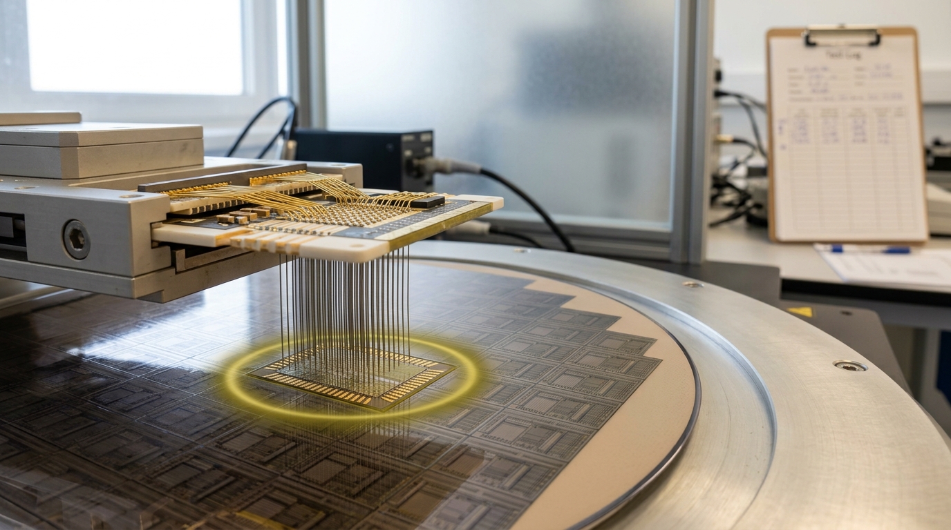
The interface, not the die
A fabless chip company does not manufacture anything. What it sends to its foundry partner is not a physical object at all — it is a file, built against a fixed and heavily documented description of a manufacturing process it will never see run. That description, the process design kit, is the actual interface between the two companies, and almost everything a design team gets right or wrong about “working with a foundry” happens inside it, long before a wafer exists.
The number of foundries capable of running that interface at the leading edge is small, and the concentration is visible in the revenue numbers. In the first quarter of 2026, the ten largest pure-play foundries together booked a record 47.95 billion US dollars in combined revenue, and TSMC alone accounted for 72 percent of it — up from 70.4 percent the previous quarter — with the remaining nine foundries dividing roughly 12.09 billion US dollars between them; Samsung Foundry held second place at 6.5 percent, and SMIC, UMC, and GlobalFoundries together held around 14.3 percent [1]. A fabless company choosing where to tape out an advanced-node design is, in practical terms, choosing among a very short list, and the terms of that choice are set almost entirely by the foundry.
This article is a practitioner-facing account of what that interface actually consists of: the process design kit a foundry hands over and what it really promises; the design rules that increasingly restrict what a layout is even allowed to look like; the gap between a layout that is clean against those rules and one that is clean against the physics the rules approximate; the multi-project wafer programs that let a design team buy a cheap first look before committing to a full mask set; the yield-learning curve a design climbs after its first silicon comes back; and the recurring, well-documented pitfalls that define how fabless-foundry relationships actually go wrong in practice.
What a process design kit actually promises
A process design kit is not a single file. It is a bundle: device models for circuit simulation, layout layers and their design rules, verification decks for design-rule checking and layout-versus-schematic checking, parasitic extraction rules, and standard-cell and input-output libraries, all tied to one specific, versioned instance of a manufacturing process. Nothing in a chip design is portable across this boundary without redoing the physical layout from the ground up; a design built against one foundry’s kit does not run on another foundry’s kit, and a design built against version N of a kit is not guaranteed to stay clean against version N+1 of the very same kit at the very same foundry.
Foundries describe the surrounding infrastructure in explicitly commercial terms, and it is worth reading their own description as a vendor claim rather than a neutral fact. TSMC describes its Open Innovation Platform as “a comprehensive design technology infrastructure that encompasses all critical IC implementation areas to lower design barriers, improve design cycle times, and accelerate first-time silicon success,” organised around an IP Alliance it calls the industry’s largest catalogue of ecosystem-partner intellectual property, an EDA Alliance of certified tool vendors, a Design Center Alliance, a Cloud Alliance, and a 3DFabric Alliance for advanced packaging [2]. The claim worth taking away is narrower than the marketing language suggests: what a foundry is actually offering through a program like this is certification — a guarantee that one named tool version, run against one named kit version, has been validated to produce a result the foundry will accept. That certification is the product. A design team that steps outside a certified tool-and-kit combination is, by definition, running an experiment the foundry has not validated.
Access to a kit is also, mechanically, gated. Kits are licensed to qualified customers under non-disclosure terms, and in more sensitive or export-controlled cases that licensing is enforced with a hardware key rather than a software login alone — a physical dongle that has to be seated in a workstation before the design-rule deck will even load.

None of this is a criticism of any one foundry; the process description genuinely is confidential and commercially valuable to protect. But it means the practical first step in any advanced-node engagement is not technical at all — it is legal and administrative, and it is usually the pacing item a first-time fabless team most underestimates.
The lock-in that follows is one of the less-discussed costs in the industry. Migrating a design between kit versions, let alone between foundries, means rebuilding physical implementation — cell placement, routing, and every rule-driven layout decision — from the physical layout upward. Analyst estimates from International Business Strategies, reported by Semiconductor Engineering as early as 2018, already put full design cost for an advanced logic node at 500 million to 1.5 billion US dollars, the higher figure tied to a particularly complex GPU design, and costs at that order of magnitude have only grown since as nodes have advanced further [10]. Set against numbers like that, a process design kit is not merely a technical dependency. Once a design is built against one, it is close to a permanent commitment for the life of that product.
Design rules built to fight the designer
At older nodes a set of design rules could be treated as a checklist: minimum widths, minimum spacings, minimum enclosures, checked layer by layer, largely independent of what sat next to what. That independence broke down as the industry pushed optical lithography well past the point where it could resolve arbitrary two-dimensional shapes cleanly, and the response was a category of rule the industry calls restrictive.
The mechanism is captured precisely in a 2009 IEEE Electronic Design Process Symposium paper written by engineers from Mentor Graphics and IBM, at the point the industry was committing to this approach for the 22 nanometre node. The paper’s own framing is direct: “the lower k1 falls, the more difficult it becomes to accurately print the desired shapes on the wafer,” and at 22 nanometres, printing an arbitrary two-dimensional shape with the immersion lithography of the day would be “very difficult… and without immersion, impossible” [3]. Restrictive design, as the paper defines it, means “limiting the type and placement of features used in designs” — gridding critical layers onto a fixed pitch so that only a constrained, lithography-friendly vocabulary of shapes is legal in the first place, trading away a large fraction of the theoretically available layout space in exchange for predictability at the pitches that actually have to print [3].
The paper’s own data makes the resulting complexity legible. A chart tracking design-rule count and rule-operation count from the 180 nanometre node through 22 nanometres shows both climbing steeply — rule count roughly tripling and the number of distinct verification operations required to check those rules growing roughly ninefold over that span — and the paper notes explicitly that operation count is growing faster than rule count itself, meaning even the rules that already existed are becoming more complex to evaluate, not merely more numerous [3]. A designer working at an advanced node is not drawing shapes and then checking them against a modest list of constraints; the constraints have become dense enough that automated, gridded, rule-compliant generation is often the only practical way to produce a layout that will pass at all.
This has a consequence worth stating plainly for anyone arriving from an older node or from digital design abstracted well above the physical layer: creativity in physical layout has not been free at advanced nodes for well over a decade. The rule deck does not describe what is possible; it prescribes what is checkable, and the two are not the same thing.
DRC-clean is not DFM-clean
Passing design-rule checking is necessary and not sufficient. Design rules are hard limits: violate one and the foundry will not accept the layout. Design-for-manufacturability rules sit alongside them as a second, softer layer — recommended rather than mandatory in many cases, aimed not at whether a feature can be printed but at how reliably it will print across the inevitable variation of a real fab. Engineers at GlobalFoundries, describing their own internal methodology, define the practice precisely: “a design is considered to have satisfying manufacturability if the design does not violate any DFM rule,” and each violation is assigned a manufacturability score between zero and one, with scores near zero flagging the most severe violations [4].
The same paper documents a specific and somewhat uncomfortable limitation of that scoring approach as conventionally implemented. Two via-enclosure violations with an identical measured enclosure value receive an identical DFM score under a rule-based system, because the scoring looks only at the violation’s own geometry. But lithography simulation of the same two sites can show one printing cleanly and the other failing outright, because the difference is not in the violation itself but in what sits around it — nearby line-ends, jogs, and other layout context that a purely rule-based, context-blind score cannot see [4]. The paper’s proposed fix — training a neural network on the mismatch between rule-based scores and actual lithography simulation outcomes, so that context-sensitive risk can be predicted rather than assumed — is itself an admission of the underlying problem: at advanced nodes, whether a specific instance of a specific violation actually matters depends on its neighbours, and a rule deck evaluated one violation at a time cannot fully capture that [4].

This is the practical reason waivers exist. A layout that is DRC-clean but carries DFM violations is not automatically rejected; it goes through a review in which a specific violation, in its specific layout context, is judged acceptable or not — sometimes by the design team’s own DFM engineers working from foundry guidance, sometimes escalated to the foundry itself for sign-off on marginal cases. Every waiver granted is a bet that a rule written for the general case does not apply at this particular site, made by someone who has to live with the yield consequences if the bet turns out to be wrong.
Buying a cheap first look: multi-project wafers
A full mask set at an advanced node is one of the largest fixed costs in the industry, and it is entirely non-recoverable if the design does not work. Multi-project wafer programs exist to let a design team avoid paying that cost before it has any evidence the design is right. A shuttle run places many unrelated customers’ designs on the same set of reticles and the same wafer lot, and divides the shared mask and processing cost across everyone on the run, so each participant pays a fraction of what a dedicated mask set would cost in exchange for a small, fixed die area and someone else’s schedule.
GlobalFoundries’ GlobalShuttle programme is representative of what a modern multi-project offering looks like in practice: it runs across a wide span of process nodes from 180 nanometres down to 12 nanometres, plus specialised offerings including RF silicon-on-insulator, RF gallium nitride, and its SLATE wafer-bonding technology, and its current base service provides participants up to 100 known-good die samples from the shared run, aimed explicitly at new customers, startups, and university partners who need a cost-effective way to validate a design before committing to volume [5]. The tradeoff is symmetric and worth stating without romanticising it: a shuttle buys cheap validation of a small design at a fixed, infrequent schedule set by the foundry, not a path to production, and a design that needs more area, a faster turn, or a process option outside the shuttle’s menu still has to go to a dedicated run.
The most consequential recent change to this landscape did not come from a traditional foundry at all. In 2020, Google, SkyWater Technology, and the design-automation company Efabless released what they describe as the first open-source, foundry-supported process design kit, built around SkyWater’s 130 nanometre mixed-signal process, together with a fully open RTL-to-GDSII design toolchain that Efabless released under an Apache 2.0 licence; within two weeks of release the kit had been downloaded more than 1,700 times, and the accompanying multi-project-wafer programme offered forty design slots per shuttle run, fabricated at no cost to the designer, with Efabless performing licence checks, data-integrity verification, and design-rule checking ahead of assembly [6]. The programme deliberately inverts the gatekeeping this article opened with: instead of a signed non-disclosure agreement and a hardware dongle standing between a design team and the rule deck, the entire kit sits in a public repository. It does not compete with an advanced logic node on density or performance, and it was never meant to; what it demonstrates is that the gatekeeping character of a foundry-fabless relationship is a commercial choice at a given node and price point, not a structural necessity of semiconductor manufacturing itself.
The yield-learning curve a design climbs after tapeout
First silicon coming back from the fab is not the end of the story; it is the start of a distinct, well-studied process the industry calls yield learning. The clearest empirical account of what that process actually looks like, and why it matters more than almost any other lever available to a manufacturer, comes from a 2004 study published in IEEE Transactions on Semiconductor Manufacturing, built from sixty-nine detailed case interviews covering solved yield, process, and equipment problems across thirty-five distinct manufacturing and process-development environments, supplemented by a further sixty-five specialist interviews [7].
The study’s production model uses a standard form for die-sort yield as a function of electrical fault density, treating faults as randomly and independently distributed across a wafer:
where A is the critical area of the circuit — the area of the design actually susceptible to a given class of fault — and F is the fault density measured per unit area [7]. The relationship is exponential in both variables, which is precisely why yield learning is disproportionately valuable: a fixed absolute reduction in fault density buys a much larger yield improvement once fault density is already low than the same absolute reduction bought when fault density was high.
The study’s fitted process-lifecycle model puts numbers on the phases a design team lives through. In the modelled research and development period, fault density starts above 100 faults per square centimetre — high enough that yield and output are effectively negligible — while up to 3,000 wafers a month exit the facility purely for process characterisation. Once systematic problem-solving begins in earnest, fault density drops by roughly an order of magnitude every six months, a rate the study’s industry respondents described as consistent with the performance of the best semiconductor manufacturers, until the learning rate flattens as random rather than systematic faults come to dominate and fault density settles near a terminal value around 0.03 faults per square centimetre [7].

The financial consequence the study derives from this curve is its central and most quotable finding: more than 70 percent of a semiconductor venture’s pretax profit is typically earned within one year of the ramp to volume production, and — having varied every lever in the model individually — the author concludes that “a rapid yield-learning rate determines profitability more than any other factor does,” more than ramping early, more than adding fab capacity, more than depressing the terminal fault density itself, and more than shrinking die size, all of which the model shows produce diminishing returns by comparison [7]. For a fabless team, the practical implication is that the weeks immediately after first silicon — running the specific test structures designed to isolate systematic from random failure mechanisms, and feeding what is found straight back into the next mask revision — are worth an outsized share of a program’s total commercial outcome, disproportionate to how they are usually resourced against the schedule pressure to simply ship.
When the curve stalls: chasing the systematic fault
Turning fault density into a yield number is straightforward once the faults are known; finding out what they actually are is not, and it is where a design team’s own layout choices come back to matter directly. Process-control monitor structures scattered through the scribe lines between dies — deliberately simple, characterisable test patterns rather than functional circuitry — exist precisely so that a specific failure mechanism can be isolated from the noise of a full, complex product die. A design team that skimped on scribe-line test structures at tapeout, treating them as wasted area, discovers the cost of that decision exactly when it matters most: during the yield-ramp period, when isolating a systematic fault quickly is worth more than almost anything else in the schedule.

When a systematic fault is found, the loop closes back on everything discussed so far. A recurring failure traced to one specific layout context — the same kind of neighbour-dependent printability problem a context-aware DFM score is trying to predict in advance — becomes evidence about where the design-rule deck or the DFM scoring model was wrong, not just about where this particular design happened to be unlucky. In a healthy foundry relationship that evidence flows back into the next kit revision or the next waiver-review guideline; in a strained one it does not, and the same failure mode reappears in the next design that walks unknowingly into the same layout context. This is one of the less visible ways a fabless-foundry relationship compounds across multiple tapeouts: the quality of the feedback loop between a design team’s own failure analysis and the foundry’s rule deck determines whether the second design at a given node learns faster than the first one did, or simply repeats it.
Common pitfalls fabless teams hit with their foundry partner
Put the pieces above together and a small number of recurring failure patterns account for most of what goes wrong between a fabless design team and its foundry partner, and they are unusually well documented for something so consequential.
The starkest is the outright decline in first-silicon success. The 2024 Siemens EDA and Wilson Research Group functional verification study, the longest-running survey of its kind, found that only 14 percent of ASIC and SoC projects achieved first-silicon success — the lowest figure recorded in more than twenty years of tracking, down from a rate that had hovered around 31 percent for most of the survey’s history [8, 9]. Eighty-six percent of projects therefore need at least one respin, roughly a quarter need more than two tape-outs before succeeding, and about 70 percent of those respins trace back to design errors introduced by changes to the specification mid-project rather than to manufacturing surprises [9]. Contributing factors named alongside the decline — advanced packaging, chiplet-based integration, EUV-driven process variability, power integrity, and high-speed protocol complexity — are, not coincidentally, close to the same set of advanced-node concerns this article has been describing from the design side [9].
Siemens EDA’s own account of the underlying cause is worth taking seriously precisely because it is a vendor with an obvious interest in verification spending making the case, which is a reason to read it critically rather than to dismiss it outright: the same account reports that 60 to 70 percent of total engineering effort on a chip project properly belongs in verification, and argues that system and software companies newer to silicon tend to underinvest in it, carrying over a “ship fast, patch later” culture that does not transfer to a discipline where, in the author’s own phrasing, “a mask set costs tens of millions of dollars” and cannot be patched after the fact [8]. Regulatory qualification compounds the problem in specific verticals; the same account singles out automotive ISO 26262 requirements as dramatically expanding the verification state space a team must cover before tapeout, well beyond what a purely functional verification plan would require [8].

The scale of what is at stake in each of those decisions has been growing for a long time and shows no sign of reversing. Analyst estimates from International Business Strategies, reported by Semiconductor Engineering as early as 2018 — years before 3 nanometre-class processes reached volume production — already put full design cost for a leading-edge logic node at 500 million to 1.5 billion US dollars, with mask-set costs alone crossing 10 million dollars at 7 nanometres and heading toward 40 million dollars at 3 nanometres [10]. Costs at that scale change the character of every pitfall discussed above: a foundry relationship strained by a mismatched PDK version, an under-scoped verification plan, or a DFM waiver granted without enough evidence is not a minor inconvenience to be absorbed and forgotten. At the design costs and mask costs current at any given node, it is one of the largest financial decisions the company will make, taken under exactly the kind of schedule pressure that the data above shows most reliably produces a second tape-out.
Predictions, with the observations that would falsify them
These are forecasts, separated from the sourced analysis above. Horizon: 15 August 2029. Assumptions: no non-optical lithography modality displaces projection extreme-ultraviolet or deep-ultraviolet lithography in high-volume manufacturing within the window, and the fabless-foundry structural model — design houses licensing process access from a small number of merchant foundries — remains the dominant arrangement for advanced-node logic.
One. Context-aware, simulation-trained DFM scoring of the kind described by GlobalFoundries’ own engineers will become a standard, foundry-supplied part of signoff at advanced nodes, rather than a research technique run only by the largest design teams with their own machine-learning infrastructure. Indicator: foundry PDK release notes at leading nodes begin listing simulation-calibrated or context-aware DFM scoring as a native signoff-deck feature rather than an optional add-on tool. Disconfirmed if leading foundries’ standard signoff flows at the end of the window still rely exclusively on context-blind, per-violation rule scoring.
Two. First-silicon success rates, as tracked by Wilson Research Group-style functional verification surveys, will not recover materially from the 2024 low. Assumption: design-complexity growth from chiplets, advanced packaging, and rising power-domain counts continues to outpace verification-productivity gains from newer, AI-assisted tooling. Disconfirmed if a comparable industry survey published before the horizon date reports a first-silicon success rate back above 25 percent.
Three. Open, foundry-supported process design kits will remain confined to mature, non-leading-edge nodes, and no advanced logic node below 28 nanometres will ship a fully open-source PDK during the window. Disconfirmed if any merchant foundry releases an open-source, foundry-supported PDK for a process below 28 nanometres before the horizon date.
None of these requires a discontinuity in the underlying technology. They follow from the structure already documented: a gatekept interface whose economics favour scale, a verification burden growing faster than the tooling that manages it, and a yield-learning process whose profitability advantage rewards speed above almost every other lever.
What to take away
Working with a foundry at an advanced node is, in practice, a long series of specific, well-defined handoffs, and almost every commercially painful failure in this article traces back to one of them being treated as a formality rather than as the actual point of contact between two companies that will never fully see inside each other’s systems. The process design kit is a certified, versioned contract, not a generic file format; the design rules encode what a specific optical process can be trusted to print, not what a designer might otherwise want to draw; a clean design-rule check is a necessary permission slip, not a guarantee that a layout will yield; a multi-project wafer buys cheap evidence, not a production path; and the weeks after first silicon, spent chasing systematic faults back to their layout context, are worth more to the eventual outcome than almost anything else in the schedule.
None of this is exotic knowledge. It is documented, in most cases by the foundries and toolmakers themselves, in the sources cited throughout this article. The pitfalls that recur are not the ones nobody warned anyone about; they are the ones that are well known and still, reliably, underweighted against the pressure to tape out on schedule.