One layer below the equipment list
A datacenter tour names its equipment the way a spec sheet does: cold plates, a coolant distribution unit, a substation, switchgear, a busway. Naming the parts is not the same as knowing how they work, and the gap between the two is where most public argument about AI infrastructure goes wrong — treating a cold plate as a solved commodity, treating grid interconnection as a paperwork delay, treating a GPU cluster’s power draw as a number rather than a waveform. This article stays one layer below the equipment list. It follows four mechanisms in turn: how a direct-to-chip cold plate actually removes heat from a package; how a coolant distribution unit keeps two separate fluid loops from ever touching; how an interconnection study and the substation downstream of it actually decide and deliver what a site may draw; and why the synchronized power swings of a training cluster show up as a power-quality event before they show up as a cooling problem. A final section follows the heat itself past the point where most accounts stop — into a second loop that puts it to use rather than rejecting it. Vendor claims are marked as such throughout, and every mechanism traced here is grounded in a standard, a grid operator’s own procedures, or a measurement someone actually published.
The cold plate: heat leaves the package before it leaves the room
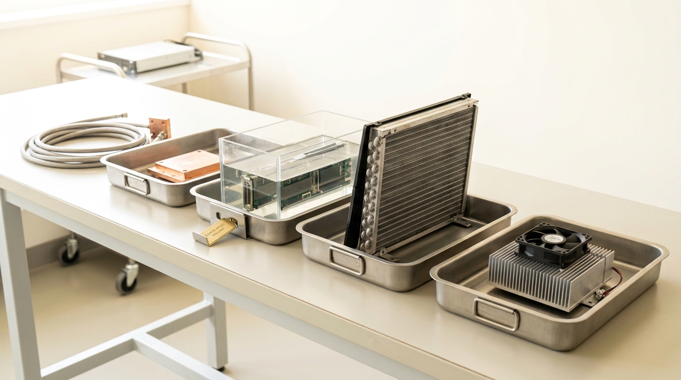
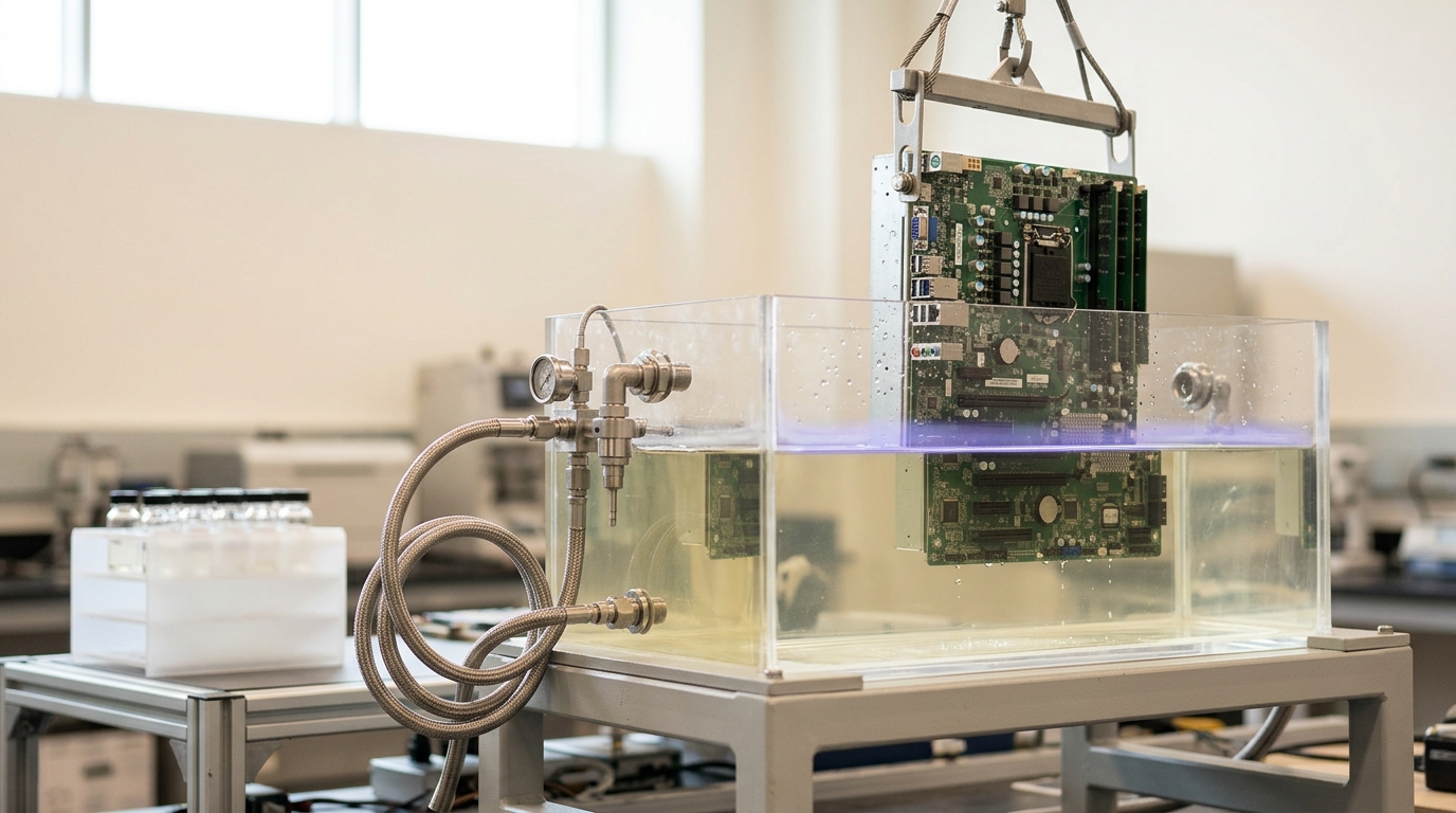
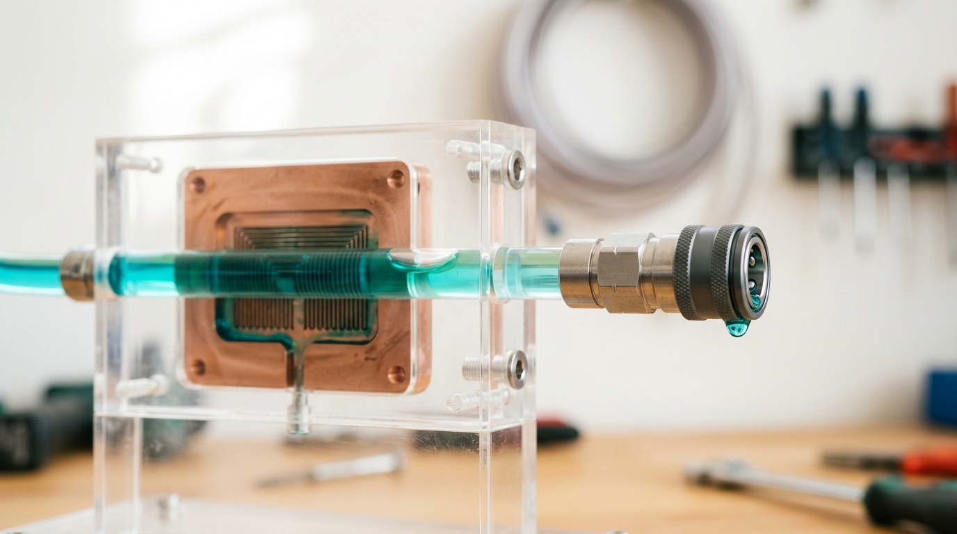
Start at the die, because everything downstream is sized to move what leaves it. A modern accelerator package rejects heat through a thermal interface material into a machined cold plate — copper or aluminum, contact-bonded to the package lid — whose underside is not a flat pocket but a dense stack of microchannels, fins or pin-arrays a fraction of a millimetre wide, cut or skived into the metal to maximize the surface area in contact with the coolant stream. ASHRAE’s Technical Committee 9.9 frames the whole problem through a single metric: thermal resistance, the temperature difference between the processor case and the cooling medium divided by the device’s power, expressed in degrees Celsius per watt. The lower that number, the more effective the cold plate, and the committee’s own dataset — built from released figures across IBM, Sun, Intel, AMD, NVIDIA and ARM sockets — traces how far that requirement has moved as socket power has climbed [1]. A cold plate is, in other words, not a passive block of metal; it is a heat exchanger engineered against a shrinking thermal-resistance budget, and the microchannel geometry is the primary lever available to hit it.
What the coolant does once it is inside the channels depends on the facility water feeding it, and ASHRAE’s naming convention makes that dependency legible at a glance. Facility water classes are now named for their own upper temperature limit — W17, W27, W32, W40, W45, and W+ — with every class sharing a common lower limit of 2°C, a simplification the committee adopted specifically because the older W1–W5 naming left equipment compliance ambiguous across the stated range [1]. That single design choice cascades through everything else in this article: a rack qualified against W45 tolerates warmer, cheaper-to-produce facility water, while a rack qualified only against W27 forces the plant to run colder loops at a higher parasitic energy cost — the same trade a cold plate’s thermal resistance budget is already fighting, expressed one level up the stack.
Scale is part of what forced this loop out of the air entirely. NVIDIA describes its GB200 NVL72 as a rack-scale, liquid-cooled system joining 36 Grace CPUs and 72 Blackwell GPUs in one 72-GPU NVLink domain, a vendor claim about a specific product rather than a general industry figure, and the company states plainly that liquid cooling in this design increases compute density, reduces floor space, and is what makes the rack’s high-bandwidth, low-latency GPU communication feasible in the first place [2]. That framing is worth taking seriously as a design statement: the cooling loop is not bolted on after the compute density was chosen — the density was chosen because the loop exists.
The CDU: one machine performing two loops at once
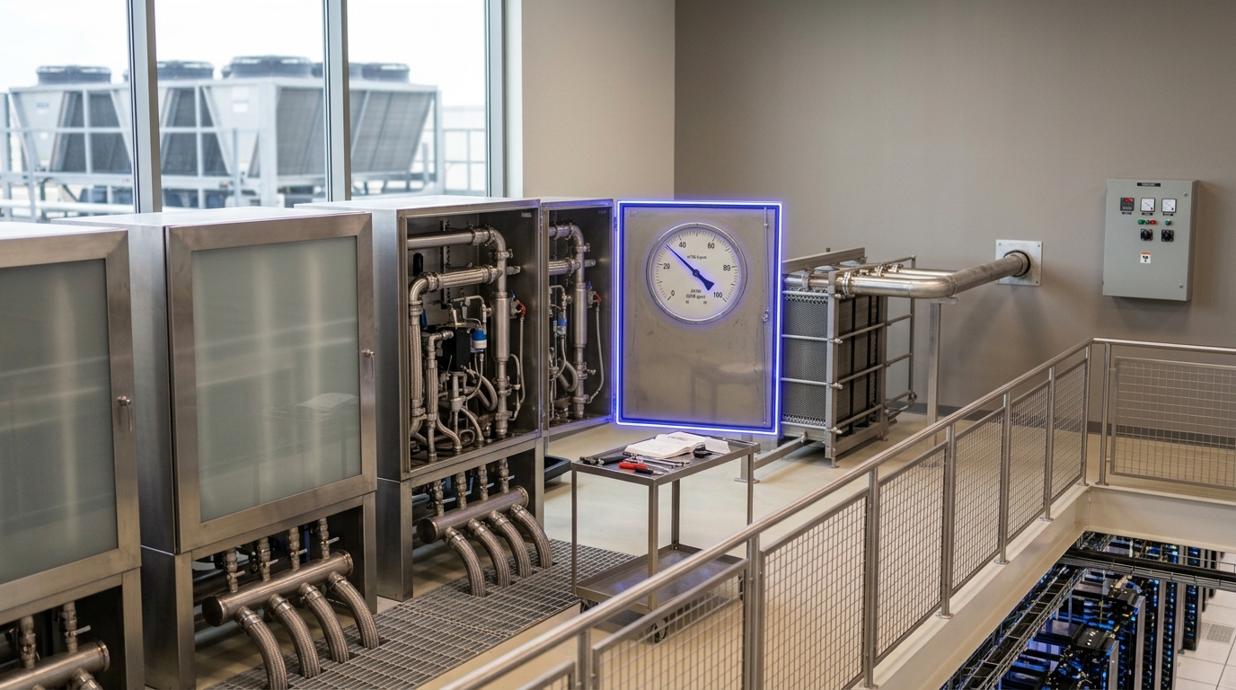
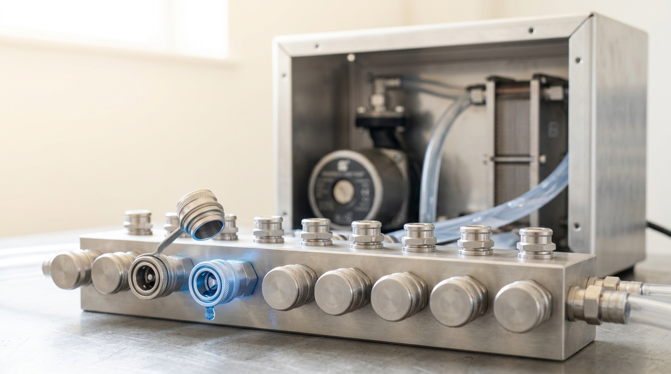
A coolant distribution unit’s entire reason for existing is that a datacenter cannot let facility water — drawn from a cooling tower or dry cooler, chemically treated to a completely different standard, arriving at a temperature the room does not control minute to minute — anywhere near the fine channels machined into a cold plate. Fouling, corrosion products or a few degrees of unplanned temperature swing inside a 300-micron channel is a failure mode a rack cannot recover from cheaply. The CDU sits at exactly that boundary: one loop on its facility-water side, a second, tightly filtered and pressure-controlled loop on its rack side, joined only through a liquid-to-liquid heat exchanger and a pump, never through a shared volume of fluid.
ASHRAE’s own worked case study puts numbers on what that separation costs in equipment. A commercial, off-the-shelf CDU sized for 750 kW served eight racks in their reference configuration, each rack carrying 40U of liquid-cooled blades plus a 2U air-cooled top-of-rack switch, with direct on-chip cold plates handling the CPU load and single-sided cold plates handling memory [1]. The same analysis is specific about what that CDU can and cannot buy back: a W27 facility loop supports up to 500 W per CPU and 12 W per DIMM with single-sided memory cooling, while a W45 loop — warmer, and therefore cheaper to produce — degrades that capability to something comparable to a well-run air-cooled room, unless the design compensates with a more capable pump and heat exchanger inside the CDU itself, fewer blades per rack, fewer racks sharing one CDU, or double-sided memory cooling [1]. None of those levers is free; each trades capital or density against the temperature the plant is allowed to run.
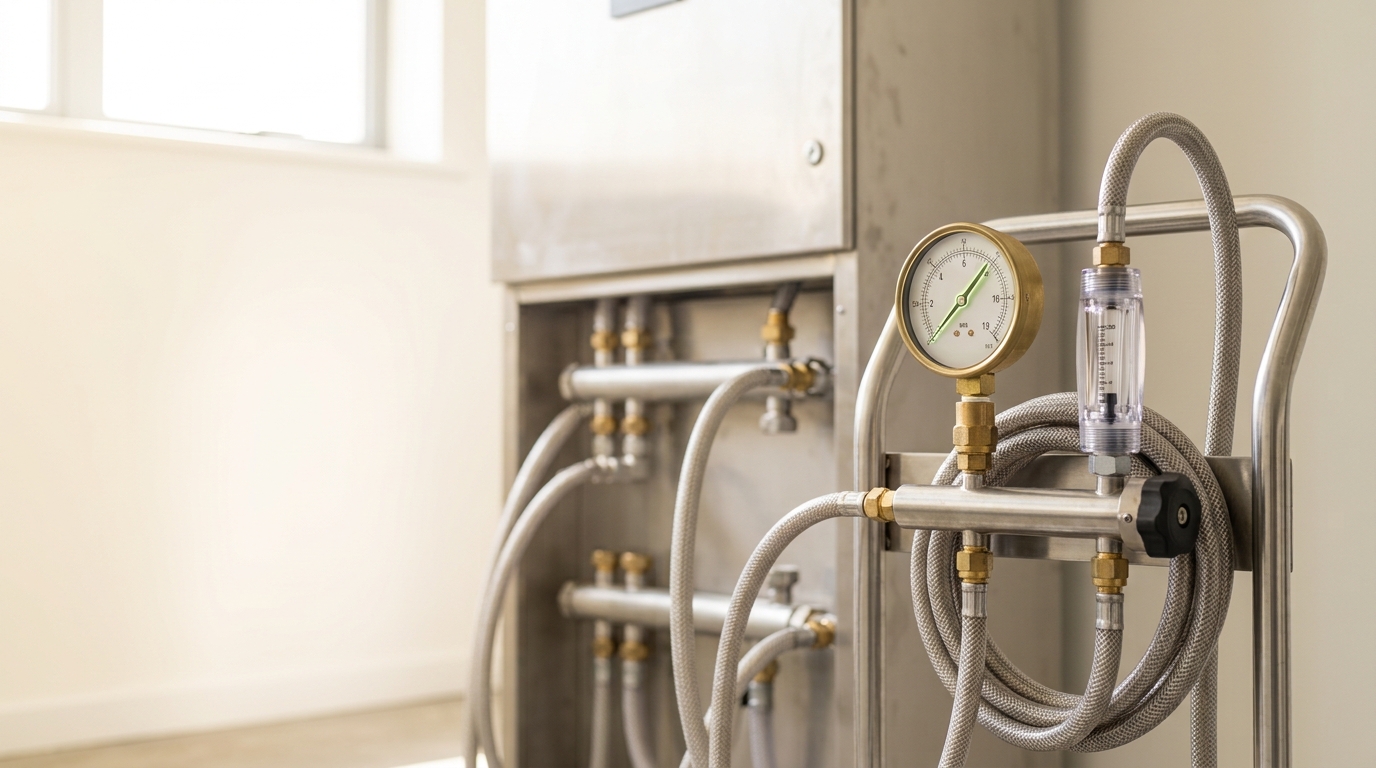
The physical interface between the two loops is the manifold: a supply and return header with a row of blind-mate quick-disconnect couplings, one pair per rack, engineered so a rack can be pulled for service without draining the loop it was fed from. Each coupling carries a spring-loaded poppet valve that seals the instant it is disturbed, which is the only reason a technician can disconnect a live cold-plate loop without flooding the row — and it is also the single most common point of failure in a liquid-cooled row, because every mated joint is a gasket that has to hold for years under thermal cycling. Where facility water reuse is discussed at all, ASHRAE flags immersion cooling as a genuine alternative to the cold-plate-and-CDU pairing for the memory subsystem specifically, but only after a materials-compatibility assessment, because the serviceability and warranty questions it raises are not hypothetical [1].
What a substation and an interconnection study actually do
Before any of that loop can be built, a very different mechanism has to clear first: the interconnection study that decides whether the site is allowed to draw the power at all. PJM’s own manual for generator interconnection requests — chosen here because it is one grid operator’s actual, filed procedure rather than a summary of one — lays the sequence out as a chain of gated studies, each triggering the next only once its fees and data are filed. A Feasibility Study runs first, a high-level pass at whether a proposed connection point and capacity are broadly workable. A System Impact Study follows, requiring the customer to supply dynamic model data alongside the impact study data itself. A Facilities Study prices and schedules whatever upgrades the impact study found necessary, and only then do the Interconnection Service Agreement and Interconnection Construction Service Agreement follow [3]. What those studies actually compute is stated in the manual in plain engineering terms: an analysis of short circuit capability limits, steady-state thermal and voltage limits, and dynamic system stability and response — the same three checks PJM runs whenever a technological change is proposed to an already-queued project [3]. A queue position, in other words, is not a reservation; it is a certificate that a specific set of fault-current, thermal and stability calculations came back clean for a specific configuration, and changing the configuration reopens the calculation.
That gating process used to run serially, one project at a time, and it became the bottleneck the industry now argues about. FERC’s Order No. 2023 replaced the serial, first-come-first-served model with an annual cluster study: a 60-day customer engagement window, a 150-day deadline for the initial cluster study and any restudy, and a further 60-day window to negotiate the interconnection agreement itself, with transmission providers now facing escalating per-business-day penalties for missing those deadlines rather than the old, effectively unenforceable “reasonable efforts” standard [4]. The order also formalized “first-ready, first-served” queuing, requiring site control — set at 90% rather than the 100% FERC had initially proposed — and staged financial deposits as a project moves through each study, specifically to discourage speculative requests from occupying a queue slot without ever intending to build [4].
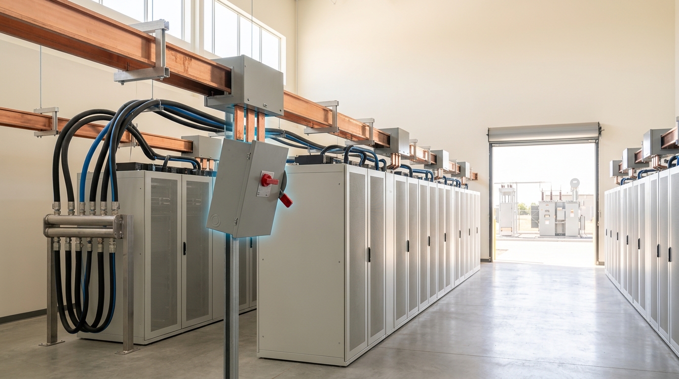
Once a project clears that process, the substation is where the delivered result becomes physical. A step-down transformer brings transmission or sub-transmission voltage down to a level medium-voltage switchgear can safely sectionalize, so that a fault or a planned outage isolates one block of load rather than the whole campus; the switchgear itself is a chain of circuit breakers and disconnects, each coordinated with a protection relay that is set, specifically, to the fault-current levels the interconnection study calculated. The equipment behind that process is itself now a constraint on how fast any of this can happen at all. The IEA’s assessment states that wait times for critical grid components such as transformers and cables have doubled over the past three years, that turbine deliveries for new gas-fired plants now face lead times of several years, and that building new transmission lines can take four to eight years in advanced economies — constraints the IEA judges put around 20% of planned data centre projects at risk of delay unless addressed [5]. Its most recent update reports that data centre electricity demand rose 17% in 2025 alone, that supply chains for gas turbines and transformers specifically have tightened further over the past year, and that a growing number of developers are turning to onsite natural-gas generation as a way to bypass grid connection delays entirely rather than wait for them to clear [6]. Read against the study process above, that is a rational response to a specific bottleneck: onsite generation does not eliminate the need for protection and stability studies, but it removes the multi-year transmission and transformer lead time from the site’s critical path.
Why a GPU cluster looks like a fault to the grid
A study clears a site for a steady-state load profile. What a large training job actually presents is not steady, and the mechanism behind that gap is worth tracing carefully, because it is the least understood part of this whole system from outside a utility control room.
Thousands of GPUs executing a training step run in near lockstep: computing together, then pausing together to communicate gradients, then computing again. On a single NVIDIA H100, that communication pause is measured as a swing from roughly 700 W down to 140 W, occurring within a handful of AC cycles rather than seconds [7]. Multiply that pattern across a cluster and the aggregate becomes a grid event in its own right: a 50,000-GPU training job at the scale of Meta’s published Llama-3 runs draws on the order of 35 MW while computing and drops to roughly 7 MW during the communication phase, a near-instantaneous 80% swing repeating every training step [7]. The grid’s own capacity to absorb that is set by physics that has nothing to do with software: generators are spinning mechanical systems whose inertia and angular momentum fundamentally limit how fast their output can change, with ramping times ranging from a few seconds to several hours depending on the unit, and bringing an additional generator online at all taking minutes to days [7]. When demand moves faster than that, the mismatch does not disappear — it shows up as voltage or frequency moving outside its safe range, and the consequences are not hypothetical: a 2023 event in which the trip of a single 1.5 GW load caused system-wide frequency deviations across Texas, and NERC’s own analysis of a 2019 disturbance in which a load oscillating at 0.25 Hz propagated across interconnections and damaged generators hundreds of miles from where the oscillation originated [7].
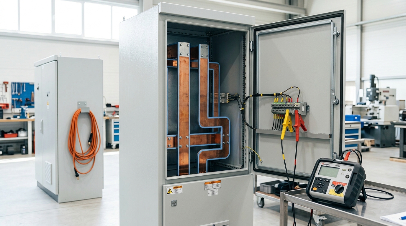
The path that swing takes through a rack’s own power electronics compounds the problem rather than absorbing it. A GPU cluster’s power chain is a cascade of conversion stages — medium-voltage AC to low-voltage AC, low-voltage AC to DC, and a final DC-DC stage at the board — and each stage has a different control bandwidth. The upstream converters, whether a medium-voltage transformer stage or a UPS front end, carry the highest power ratings and the lowest control bandwidth, which makes them the global bottleneck for a rapid transient; the voltage regulator modules sitting right next to the GPUs can switch at tens or hundreds of kilohertz, but their fast local control loops can only buffer small amounts of energy over millisecond-to-microsecond timescales, nowhere near enough to smooth a swing that persists for whole AC cycles [8]. Measured directly on GPU testbeds, current draw has been observed swinging from near zero to 25–30 amps within a fraction of a second during both training checkpoints and ordinary inference load transitions, fast enough that local capacitors and PSU control loops smooth the sharpest edges but not the abrupt negative transients that follow, which pose their own overvoltage risk further up the chain [8]. Regional standards then set the tolerance this whole cascade has to fit inside: IEEE Standard 519-2014 caps total harmonic distortion at 5% at the point of common coupling in North America, voltage regulation is typically held to within ±5% in North America and up to ±10% in some European jurisdictions, and power factor is commonly specified in the 0.95–0.98 leading range — limits that were not written with millisecond-scale, correlated multi-megawatt swings in mind [8]. Rack power itself has moved the goalposts on all of this: training racks that drew 10–20 kW a few product generations ago now exceed 100 kW, with some cabinets reaching 350 kW [8].
Grid operators are treating this as a distinct reliability category rather than an ordinary large-customer nuisance. NERC’s own 2026 reliability guideline names AI data centers explicitly, alongside cryptocurrency mining and hydrogen electrolysis, as loads whose variable and cyclical profiles can introduce forced oscillations into the bulk power system, warns that oscillations at higher frequencies carry a risk of subsynchronous control or torsional interaction with nearby generators, and recommends that transmission operators and reliability coordinators build phasor measurement unit monitoring below 10 Hz and point-on-wave measurement above it directly into how they watch these loads [9]. The guideline is equally direct about what it expects from the load side: voltage and frequency ride-through curves modeled on the same standards already applied to generating resources, coordination with under-frequency load-shedding trip settings, and — where ride-through cannot be established — mitigation through technologies such as battery energy storage, static synchronous compensators, GPU firmware ramp-rate limits, and rack-level energy storage [9].

Buffering the swing: what sits between the rack and the busway
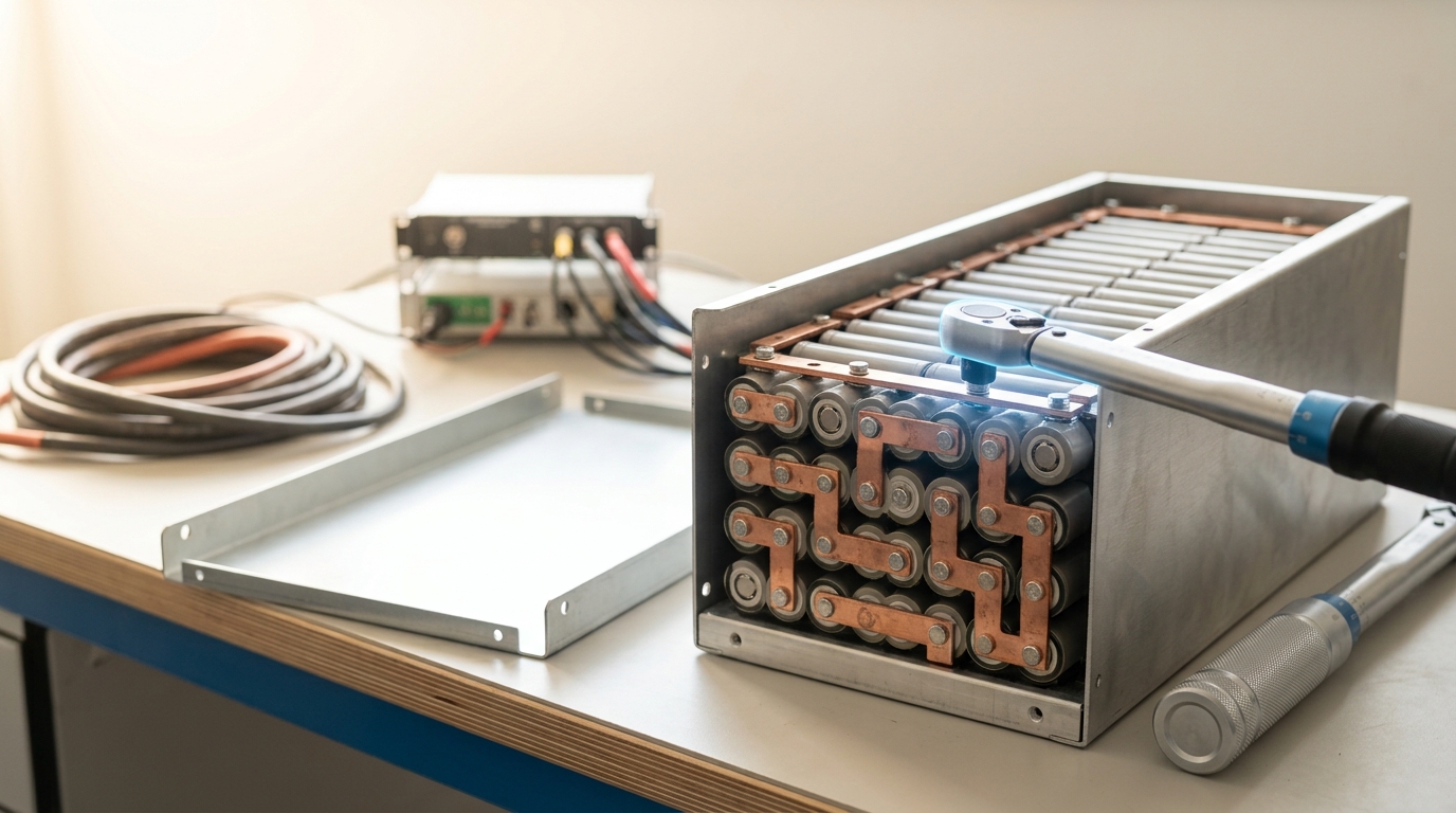
The mismatch between how fast a GPU cluster’s load moves and how fast a generator or an upstream converter can follow it is not a problem either end of that gap can solve alone, which is why the mitigation architectures on offer all place something new in the middle. EasyRider, a rack-level power architecture published against exactly this problem, combines a passive input filter that attenuates the highest-frequency transients with an actively controlled auxiliary energy store — batteries or supercapacitors — operating at 400 VDC, sized specifically to absorb the lower-frequency, longer-duration swings the passive filter cannot touch [7]. Its own reported performance is a useful anchor for how large a job this actually is: the design’s DC-DC converter holds rack output voltage within 0.7% of its rated value even when rack power itself is changing at ramp rates as high as ±200 kW per second, filtering the load before it ever reaches the busway the facility monitors [7].
That is one published design, not an industry standard, and its authors are explicit that it targets the rack rather than the grid connection. NERC’s guideline points at the same category of hardware — battery energy storage, static compensation, rack-level storage, ramp-rate-limited GPU firmware — but from the operator’s side of the fence, as tools it expects large-load interconnection agreements to specify rather than assume [9]. The two perspectives describe the same physical requirement from opposite ends of the wire: something with a fast enough control loop and enough stored energy has to sit between a training step’s millisecond-scale power swing and the seconds-to-hours timescale on which a spinning generator can actually respond, because neither the GPU’s own local capacitors nor the upstream utility connection can cover that gap by itself [8].
The heat that doesn’t have to be wasted
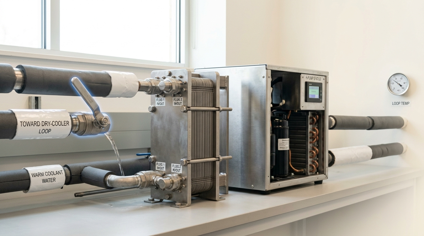
Every mechanism traced so far ends with heat leaving a die, crossing a cold plate, and arriving at a CDU already carried in a liquid rather than dispersed into room air — which matters here because a liquid is also the only practical form that heat can be in for reuse to be worth attempting. A dry cooler or cooling tower simply rejects it to ambient air or the wet bulb; a second loop, tapped off the same CDU return line before it reaches the dry cooler, can instead carry it somewhere the heat has value.
The limiting factor is temperature, not volume. Oak Ridge National Laboratory’s own published energy dataset for its Frontier exascale supercomputer — the facility’s actual telemetry, not a projection — records power draw ranging from 8 to 30 MW and waste heat leaving the system at only 30–38°C, a temperature the paper is explicit is too low for compatibility with standard HVAC systems without further treatment [10]. That is the general shape of the problem for any liquid-cooled cluster: cold-plate loops are engineered to run cold, precisely because a colder loop is a more effective heat sink for the die, which leaves the return water too cool to use directly for space heating or domestic hot water.
A companion ORNL study worked through the fix: a high-temperature heat pump inserted between the CDU’s return water and a district heating loop, evaluated across six thermodynamic cycle configurations using low-global-warming-potential refrigerants capable of delivering water up to 120°C [11]. Their recommended configuration — a single-stage cycle with an internal heat exchanger, economizer and parallel compressor, using the refrigerant R1234ze(Z) — is reported to cut 33,100 to 33,200 metric tons of carbon dioxide emissions annually at the megawatt scale modeled, equivalent to 85.4–85.6% of what a natural-gas boiler would emit to deliver the same heat [11]. The mechanism generalizes past this one campus: the heat pump’s job is exactly the inverse of the cold plate’s. A cold plate moves heat from a hot package into a cool loop; a heat pump moves the same quantity of heat from a cool return loop up to a temperature a building can actually use, spending electricity to make that lift rather than to discard the heat entirely.
What would change this account
These are forecasts, kept separate from the sourced analysis above. Horizon: August 2030.
One. Rack- or row-level active power buffering — batteries or supercapacitors sized specifically to smooth GPU synchronization swings, in the mold of EasyRider’s architecture — moves from a research prototype into a standard line item on new large training deployments, because the alternative is an increasing rate of trip events as gigawatt-scale training campuses multiply. Observable indicator: whether new large training deployments disclose dedicated transient-buffering hardware as a standard design element rather than an optional add-on. Disconfirmed if large new training deployments through the horizon continue to rely solely on generator ramping and grid-side reactive equipment, with no rack- or row-level energy buffering in general use.
Two. NERC’s 2026 guideline language on large-load oscillation and ride-through moves from voluntary reliability guidance into binding interconnection agreement terms at multiple major grid operators, following the same path FERC’s cluster-study reforms took from proposal to enforceable tariff. Disconfirmed if, by the horizon, the guideline remains non-binding recommended practice with no major transmission operator incorporating enforceable large-load ride-through or oscillation limits into its standard interconnection agreements.
Three. Facility water temperatures specified for new direct-to-chip deployments trend toward the colder end of ASHRAE’s classification (W27 or below) rather than the warmer end, because socket power keeps rising faster than cold-plate thermal resistance is improving. Disconfirmed if new large liquid-cooled deployments are predominantly specified at W40 or warmer by the horizon.
Four. Heat-pump-upgraded waste-heat reuse becomes a routine design option offered alongside dry cooling for new liquid-cooled campuses sited near heat demand, rather than remaining confined to single demonstration sites like Frontier’s, because the marginal cost of tapping an already-liquid CDU loop is small next to the cost of building the loop in the first place. Disconfirmed if, by the horizon, heat reuse remains limited to isolated pilot projects rather than appearing as a standard offered option in new liquid-cooled campus design.
None of these requires a discontinuity in the underlying physics. Each follows from a mechanism already documented above: a control-bandwidth mismatch that has to be filled by something, a reliability guideline that follows the same enforcement path earlier interconnection reforms already took, a thermal-resistance budget under continuous pressure from rising socket power, and a liquid loop that was always going to make the heat inside it easier to reuse than air ever was.
What to take away
None of the four mechanisms in this article is exotic on its own. A cold plate is a heat exchanger sized against a thermal-resistance budget; a CDU is a boundary between two loops, enforced by a pump, a heat exchanger and a row of self-sealing couplings; an interconnection study is three specific calculations — fault current, thermal and voltage limits, dynamic stability — repeated every time the configuration behind a queue position changes; a power-quality event is what happens when a load’s control bandwidth outruns the grid’s. What is new is the scale and the correlation: thousands of accelerators stepping together turn a manageable transient into a multi-megawatt swing that looks, to the instruments watching a busway, like the leading edge of a fault rather than a training job doing its work. Understanding the mechanism at each layer — the channel, the coupling, the relay, the control loop, the valve that decides whether heat is wasted or reused — is what separates reading a megawatt figure off a spec sheet from knowing what actually has to go right, in order, for that figure to survive contact with a real grid.